Wednesday 11 October 2017

WD Mindmap

As a response to some of the drawings I have been reviewing, Please consider the following files.
1. Is the mindmap image of a variety of content elements that I consider when working on WD.
2. Is an outline of text associated with the image.
Use them as you see fit, they may be of some benefit.
Also please refer to the WD checklist, as the drawings as printed, are missing many elements.
Revit also seems to be taking a toll on basic required graphics conventions.
Some project submissions are in a very basic state.
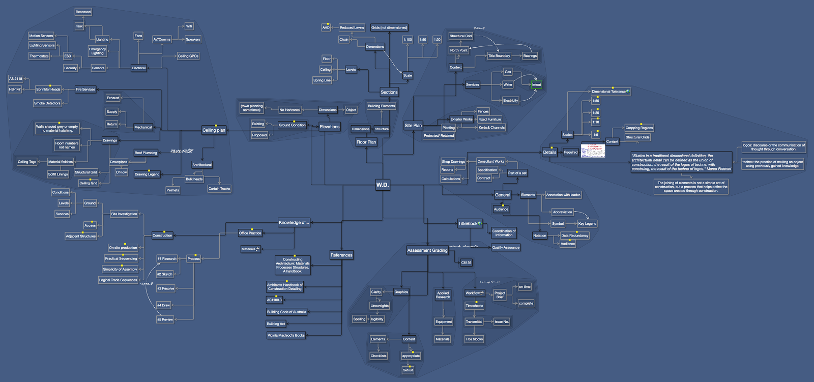
  1. W.D.

    1. DetailsSelect details based on. > unfamiliar materials > atypical junctions or connections > to maintain an overall design language
      1. Required
      2. Scales
        1. 1:5Joinery Emphasis on fixings or routing profiles
        2. 1:10Typical scale for most junction details. Ensure enough 'field of view' is included to create context and meaningful relationships with the surrounding elements.
        3. 1:20> Complex Internal Elevations > Wall sections, where 1:10 details will not be required, but enough complexity to not justify 1:50 sections. 1:20 Section details are typically called out from a 1:100 section, or a part section off plan.
        4. 1:50> Complex plans, Elevations. > Basic Internal Elevations. > Sections: Primarily used to place 1:10 call out details. A tricky scale for sections, as there is a tendency for placing too much information. An early print is suggested to remind how much information is actually useful at this scale.
        5. Dimensional Tolerance
          Link: http://www.vba.vic.gov.au/media/latest-news/article/2015/guide-to-standards-and-tolerances-2015The aim of structural tolerances is to ensure that 'as built' imperfections are no greater than those assumed in the structural design calculations. Depends on the construction method and materials. @1:100 scale, less than +- 10mm is difficult/ costly to achieve. Precast concrete has a wide constructional tolerance. Steel does not, as it is a more reactive material.
      3. "Elusive in a traditional dimensional definition, the architectural detail can be defined as the union of construction, the result of the logos of techne, with construing, the result of the techne of logos." Marco Frascari
        1. logos: discourse or the communication of thought through conversation.
        2. techne: the practice of making an object using previously gained knowledge.
        3. The joining of elements is not a simple act of construction, but a process that helps define the space created through construction.
      4. Context
        1. Structural Grids
        2. Cropping RegionsMake sure that enough of the detail includes how are elements are completed, or the extent gives some wider indication of why the detail needed to be drawn.
    2. Site Plan
      1. Services
        1. Gas
          1. In/out
        2. Water
        3. Electricity
      2. Context
        1. Structural Grid
        2. Title Boundary
          1. Bearings
        3. North Point 
      3. Exterior Works
        1. Kerbs& Channels
        2. Fences
        3. Fixed Furniture
        4. Planting
          1. Protected/ Retained
    3. References
      1. Constructing Architecture: Materials Processes Structures, A handbook.ISBN: 978-3-7643-8631-3
      2. Architects Handbook of Construction DetailingISBN: 978-0-470-38191-5
      3. AS1100.3Obsolete, out of date.
      4. Building Code of Australia
      5. Building Act
      6. Viginia Macleod's Books
    4. Ceiling planThe ceiling plan is like a floor plan, or roof plan, in that you do not highlight the underlying structure, (this is the domain of the consultants). Impacts such as bulkheads are indicated and dimensioned.
      1. Mechanical
        1. Supply
        2. Return
        3. Exhaust
      2. Drawings
        1. Walls shaded grey or empty, no material hatching.They are existing
        2. Room numbers not names
        3. Material finishes
          1. Ceiling Tags
          2. Soffit Linings
        4. Structural Grid
        5. Ceiling GridCan be used for dimensioning clarity. "NOTE: All ceiling elements to be set out centered to tile, unless otherwise noted."
      3. Drawing LegendOften Considered a checklist in it's own right. As many projects often specify known products, with a known quality over time. (supplier kick backs!!!)
      4. Electrical
        1. Lighting
          1. Task
          2. Recessed
        2. Emergency Lighting
        3. Ceiling GPOs
        4. Sensors
          1. Security
          2. ESD
            1. Thermostats
            2. Lighting Sensors
            3. Motion Sensors
        5. AV/Comms
          1. Speakers
          2. Wifi
        6. Fans
      5. Fire Services
        1. Sprinkler HeadsLight Areas 1 Sprinkler for 21m2
          1. HB-147
          2. AS 2118
        2. Smoke Detectors
      6. Roof Plumbing
        1. Downpipes
        2. O'Flow
      7. Architectural
        1. Bulk heads
        2. Pelmets
        3. Curtain Tracks
    5. General
      1. Elements
        1. Annotation with leader.
        2. Abbreviation 
        3. Symbol
          1. Key Legend
      2. AudienceDefines data required.
      3. Notation
        1. Data RedundancyDo not duplicate your own notation, as it may create discrepancies. NEVER duplicate consultants notes. List only relevant A.S. Codes. Notes should not replace the need for a proper specification.
        2. AudienceWho is the note intended for?
      4. Part of a set
        1. Consultant Works
          1. Shop Drawings
          2. Reports
          3. Calculations
        2. Specification
        3. Contract
    6. Assessment Grading
      1. Graphics
        1. Clarity
          1. Lineweights
          2. legibility
            1. Spelling
      2. Content
        1. SetoutDimensions
        2. Elements
          1. Checklists
        3. appropriateArchitectural emphasis, not consultant specific information.
      3. Applied Research
        1. Equipment
        2. Materials
      4. Workflow
        1. Timesheetsa record of your efficiency
        2. Transmittal
          1. Issue No.
        3. Project Brief
          1. complete
          2. on time
        4. Title blocks
      5. C6136
    7. Floor Plan
      1. Dimensions
      2. Structure
        1. Building Elements
    8. Elevations
      1. Ground ConditionDo not hatch the area between the proposed ground line and the existing ground line.
        1. Existing
        2. Proposed
      2. Dimensions
        1. Object
        2. No Horizontal
          1. (town planning sometimes)
    9. TitleBlock
      Link: https://docs.google.com/presentation/d/1RZV3jkGabPyqTEHMlEcOMV0Tr3boTrNJkqMSUx2zOOM/edit?usp=sharing
      1. Coordination of Information
      2. Quality Assurance
    10. Sections
      1. Levels
        1. Floor
        2. Ceiling
        3. Spring Line
      2. Grids (not dimensioned)
      3. Scale
        1. 1:100
        2. 1:50
        3. 1:20
      4. Dimensions
        1. Chain
        2. Reduced Levels
          1. AHDAustralian Height Datum
    11. Knowledge of...
      1. ConstructionThere must be a fundamental understanding of how elements are connected or what is their primary purpose
        1. Site Investigation
          1. Ground
            1. Conditions
            2. Levels
            3. Services
          2. AccessTo and throughout the site
          3. Adjacent StructuresStructures or elements, that may affect or be affected by construction.
        2. On site productionThe layout of a building or buildings on site should wherever possible recognise the requirements of site access, material handling and construction sequences. Access to and around the site may impose limitations on the size of members that can be used. These limitations may, in some cases, dictate the whole philosophy of the frame design. For example, a design which utilises a truss to give a large, clear span, is inappropriate if the truss is too large to be assembled on site and then erected. In addition to physical constraints, the design philosophy may be dictated by time constraints on site. A `construction led' approach means that the construction programme has a major influence on design decisions. For example, a restrictive construction programme may necessitate the incorporation of pre-fabricated components in the design. Pre-fabrication may also be appropriate for export work when labour costs on site are high, or there is a shortage of skilled labour.
        3. Practical SequencingDetermine a possible construction sequence that would satisfy the requirements of a main contractor, whilst maintaining stability of the structure at all stages of construction.
        4. Simplicity of AssemblyStandard, simplified connections should be used wherever possible. Time and cost penalties are often associated with less familiar forms of construction because of the `learning curve' effect.
        5. Logical Trade Sequences
      2. Office PracticeDrawings can reveal the construction SEQUENCING. that is when and where materials are to be delivered onto site.
        1. ProcessMark Up Sets
          1. #1 Research
          2. #2 Sketch
          3. #3 Resolve
          4. #4 Draw
          5. #5 Review
      3. Materials

Thursday 24 August 2017

Design Notes Post

Pre Design Stage
This is by no means a definitive checklist.
But gives some indication of the process and background data required to work on this project.
While this information may not be directly included on the final submission, not researching this data will be evident in the errors within the project, or the thoroughness of the design response.

Tuesday 11 July 2017

Assessment Categories -Context


CONTEXT

While a concept presentation may place the building into a distinctly different context, (Dante's inferno for example), this act allows the reader to re-interpret a meaning for/of the purpose/intent/expectation of the design.


Context is assessed in a number of ways.

  1. @ pre-design stage; research, (data gathering and analysis) provides clear and accurate information for the designer to consider and proceed with an appropriate design response and project direction, (line of enquiry). [Audience: In house, co-workers, design team, (potentially client or lawyer).]
  2. @ concept design stage, context is a basis for the design response. How the designer responds to context establishes a conceptual and/or programmatic framework for further development. As indicated above, the physical context in which the site is situated, may not be immediately obvious, or more implied rather than inherently literal. [Audience: Client, Marketing, Peers.]
  3. @ design development stage; (pre town planning). Context becomes concrete. Materials selection and existing fabric are accurately represented to clarify any doubt or ambiguity for contractual/ legal approval. [Audience: Client, Consultants, Co-workers].

Thursday 25 May 2017

Design Vids

Sendai Media Centre

Pompidou Centre


Maison d Verre


Tuesday 23 May 2017

Some W.D. Scribbles.

Worth understanding the forces involved to determine an economic, elegant and plausible solution to the design of the tech.

Remember Architectural details are about the finish and jointing and connection of materials and planes. Research is required for understanding the fixing and connection requirements, and span and properties of the materials being specified.

Here is a thought about the blockwork wall at the lower floor store under the grandstand seating.

Monday 22 May 2017

WD Grading

This is the rubric header/ criteria for how grading works.

Assessment ProjectProject Brief [Proforma]Project Brief [On Time]Project Brief [Filename]Project Brief [Format]Project Brief [Efficiency]Project Brief [Workflow]Project Brief [Completion]Text [Printing]Text [Media]Text [Titleblock]Text [Consistency]Text [Elements]Text [Dimensions]Text [Grid]Graphics [Line Styles]Graphics [Backlining]Graphics [Material Hatch]Graphics [Sheet Layout]Graphics [Elevations]Building Elements [Objects]Building Elements [Details]Building Elements [Research]General FeedbackScoreGrade
10.00%30.00%30.00%30.00%Task WeightingScoreGrade
10.00%10.00%5.00%5.00%10.00%20.00%40.00%5.00%5.00%10.00%10.00%30.00%30.00%10.00%30.00%30.00%20.00%10.00%10.00%40.00%40.00%20.00%Category Weighting
Will explain further in class, what each of these elements means, although hopefully, it is somewhat self explanatory.

Monday 1 May 2017

Been as while.

Okay, It's been a while. Here are the summary briefing notes for WDMPO2
1. Read Both the structural information (for sizes, and possible solutions) with the design drawings, (for intent), The design drawings are the brief.

This is actually a FUN project. (No, it's not an acronym). This is where design merges with WD. Think previous project entry canopy. It very much emulates what would happen in an office. You may not have been involved in the design stage of the project, but you are now.
Determine a basic grid setout.

Analyse and interpret the materials palette.
Start working out/ (unlocking) some of the key connection details, that set out some of the structure.
1. Box Gutter Detail. Make the section as shallow as possible. A box gutter depth of 175mm is as shallow as I would like. Set the roof angle to 1.5 or 2 degrees, they do not need to be symmetrical. Also consider cutting into the roof beam.

Building will have a variety of materials.

Tuesday 28 March 2017

Catching up.

Trying to post up all the notes from the last 2 weeks WD and DES to clear my desktop, so here goes...Post-analysis under each image...

 Okay, this 1st one, was actually a scribble from 3rd year, but most of my class notes are largely interchangeable. This looks at brick veneer wall, and considers the arrangement of the various skins or lines that constitute that wall. With the following question. What are the architectural and structural implications if we reorganise the sequence of these lines, and expand the spaces in between?
(Think about this one for a while).

 WD: The usual submission requirements.
Timesheets and Markups are obligatory.
[RANT MODE ON] THERE ARE STILL SOME STUDENTS WHO HAVE NOT PRINTED LARGE FORMAT SETS, AND I HAVE YET TO SIGHT THEM. YOU KNOW WHO YOU ARE, AND I WILL BE INSISTING ON SEEING THEM NEXT CLASS. [RANT MODE OFF]


This one is a design image. Covering the crucial need to not let revit control the graphic outcome of your projects.

  • all arrows point up (not down)
  • do not use default hand rails.
  • simplify furniture, most times outlines are enough.
  • use a scale bar not an odd ratio.
  • small key legend is preferable to room tags.
Use Virginia Macleod's Books as a base graphic style/ bench mark. Clean and simple lines, tones are better than hatches.

Simple message here. Design is inclusive, that is the influences (dare I say context again!!!) inform the scheme and graphic.
Do not forget the data tower, it is a requirement in the brief.
Also information being collected from the site has to be conveyed to the general public on site. This has to be conveyed in the final scheme. Key physical elements have to be included. Bike paths, river, trees and contours (minimum, not negotiable).


 The plans have to include more than a nod and a wink to the BCA. At the very least, Doors need to open in the path of travel. Stairs need to comply. some of the sections I have seen, have conveniently ignored stair geometry. Make sure they work.


This image is about the incongruities I am seeing about the graphic quality of the floor plans. Each plan graphic needs to relate to the floors above and below them.

Design one again, tones not hatches.
Glass as black.

WD. This is a critical detail, I am seeing the same solution a number of times, which is far from convincing.
another pick just reminding ppl of the details required for this project.

Monday 6 March 2017

WD#5

so little time, so much fun...
Messy scratchings for the entry canopy.
Even messier musings on the roof plan.
Remember:
Look up the A.S. Codes for Fall Arrestors and include them.
Dimension to grid all penetrations through the roof
Pay close attention to the roof plumbing.
"remember the raindrop"

Wednesday 1 March 2017

Concept Mapping Exercise

Step 1 & 2

1. Create a 'mind cloud' an unfettered word association from which to draw numerous conceptual 'seeds'
a) do not spend long at each node. (total time about 45mins.)
b) do not try to reverse engineer an outcome.
c) adjectives use can apply to building descriptions or maybe not.
d) draw on your knowledge of architectural history.
e) bring in conclusions and ideas from the precedent study.
e) draw on subjects you are passionate about, and that may inform you design position.
f) the map should be by definition, uniquely personal.
_______________
Take a break
_______________
2. Combine these constituent bits into a collective grouping/ some contradictory bits may 'virally' enter the mix to mutate later on...
a) with lines, colours, proximity
b) write and begin sketching or image collating 3 or 4 options.

Monday 27 February 2017

canopy sketch

as requested

WD Elevational Scribbles

Here is the screen grab from the not quite working white board... use it as you can.

Thursday 23 February 2017

#3

For next week...
Site Plan/ Floor Plan 1:100 or 1:200
2 Elevation Studies 1:100
1 Section 1:50

Minimum Cad, as I want really clean line-work. Not working drawings, but more like detail magazine.

Expand on the mind map to be able to present a cohesive conceptual framework and response to project brief.

As many concept sketches and proto-plans that can suggest a possible solution.
Also look at the website geometries of Paul Bourke
Interview with Peter Zumthor.